jueves, 2 de marzo de 2017

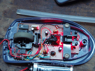
Optical Synthmouses


If you are interested in making your own SinteMouse, here is a step-by-step tutorial I wrote for simplicity. 

Http://www.instructables.com/id/Bend-an-Optical-Mouse-to-hear-surface-textures/ 
The editors of instructables liked the tutorial, they put it featured on the main page and they gave me "pro membership" for a year :) 
Several thousand visits! Positive feedback! New ideas suggested by readers! Cool!


A 1 minute video of one of this hacked mouses in action

https://www.youtube.com/watch?v=luZazXOj9Mc


Idea:
This circuit bending materializes my original premise of "listening to the textures of objects" that triggered the development of SoundPaint. Program for Java, in Processing language that tries to fulfill the premise by digital means, with the possibilities and limitations of that medium. ( Http://ignaciodesalterain.blogspot.com/2011/06/soundpaint.html ) 


The "real" surfaces were still in silence. After an unsuccessful attempt to intervene a barcode reader pencils for this purpose. 

I made a question to myself while replacing an old wand barcode reader at work: "Can I hear the bar codes if I somehow connect the sensor of the pencil to a speaker?" "Similar to the hacked ball mouses, it would be a phototransistor of some kind connected to a speaker.." 

Then I said to myself, "how about listening to any texture on any surface?... Woooaahh!"


Research process: 
On December 13, 2011, I decided to continue researching my old optical mouse. I used it for years until I got a PS2, I changed it to free the USB port of my pc. 


When I removed the plate I saw that it has a hole down that shows the "belly" of the chip, with navel and everything. 

Behind the small hole there is a microcamera of very low resolution and high refresh rate. The pic shows the chip/board upside down, the hole in the board and the chip cover out, on the board.

I was investigating how it works. And how to intervene that camera to see the image on a pc, but it is complicated and the Instructable I read requires a specific chip. 

Http://www.instructables.com/id/Mouse-Cam/ 
Anyway this does not solve my premise. 

I found a Crazy Mouse that runs away when you want to grab it :) 

Http://www.instructables.com/id/Crazy-Mouse/ 

For gamers, you can add "rapidfire" to the mouse click with a 555, or 40106. 

Http://www.instructables.com/id/Add-a-rapid-fire-button-to-your-mouse-using-a-555-/ 

But I found nothing useful to my cause ... 

So I kept on opening my path, cutting bushes, marking trees. 


It's just the same pierced chip, it's "belly" and "back", without the cover and with it in place.

I pierced the chip with a wick of the diameter of the sensor, 5mm.
I put the cap back under the chip.
I glued the sensor in the hole on the top side, with the gun.
I cut the tracks that originaly fed current to the LED and weld cables and resistance of 270 Ohms. 


And so I did the first test in which I tried to "listen" to the newspaper. 

It did not work. 

The LED light interferes the sensor behind, above the board. 
The solution was to paint the entire back with matte black paint so that light only enters the hole under the mouse. 
Three times to avoid any transparency.


Now the problem was the reverse, I could not completely saturate the sensor with the little light coming through the hole after bouncing on the paper / wood / cloth etc ... 

The signal was barely audible, I connected it to the base of a transistor to amplify it (BC337).
At the output of the transmitter of the transistor is heard acceptably well ... 
You can see the 337 with its three legs between the sensor and the 9V battery in the photo below.


When I made it work I started to move the mouse over everything around me and listen. 
I accired a notion of "how a texture would sound", an interesting "pseudo-sinestesic" sensation so to speak. 
A power like those of the X Men or Neo watching the Matrix, you know. 
The cross on top of the mouse is exactly over the sensor, so I know where to aim, what am I hearing.


Scouting for the limits of the system I generated this image. 
Some patterns attempt to generate square waveform (-_-_-_-_), other sawtooth (/////). 
And sinusoid: the sinusoid oscillates rounded, similar to the movement of a pendulum, rises and falls gradually. 
I generated patterns on different scales to see how high and low the pitch of the sound can be. 
The device has a very fine resolution, I can hear the lines of a notebook sheet and thinner lines. Thin enough, I guess. Pierced surfaces like mosquito nets, combs or a protoboard are fun to hear. 
I can not hear well some reflective surfaces like glossy paper or enamelled ceramics. 
For some time I gave up on the background noise problem, the mouses work well enough to have fun with. 


22/05/2017 Update:

I recieved some light sensors that should be more sensitive than the ones I can get at local shops. The ST-1CL3H was a game changer for my project.

Using those I no longer need a +9V,0V,-9V power supply, just a 5v stabilized transformer will work fine.
No transistor, no operational amplifier.

Just the sensor plugged to the 5v with a resistor and a cable to take the signal out of this.


Much better sound quality, and noise signal ratio. 


miércoles, 1 de marzo de 2017

Color to sound and Grayscale to sound.

Idea: 

While finishing the first non optical mouth sinths, the ball ones, I came up with another circuit bending //link wiki project.
 

Some systems that I maintain in my work have barcode readers plugged in.
 These have a LED emitter at the tip and a sensor behind that gets the light bounced off a hole. 
The voltage at that light sensor varies with the opacity of the plane on which the pencil stands. 

Passing through a bar code generates a squareish wave at the sensor output that can be decoded as numbers and letters by the digital system.

It can also be heard, as any signal within the audible frequecy range. The voltage varies with the white-to-black passage of the bars or whatever we pass the pencil over. That wave can be expressed by a speaker as sound. 

Anything, a photo, a drawing, a wooden board, monolithic floor, fabric, if it has some kind of texture, or lines, or holes, will produce variations in the sensor as the pen passes over it.
 

Conceptually, this project could be between
Circuit Bending (My project isn't "chance based", as CB is defined, I mostly know what I'm doing)

And

Hardware Hacking https://en.wikipedia.org/wiki/Hacking_of_consumer_electronics


Process:

I then put to work on some broken reading pen of the ones that are to be thrown away at work.

It soon found out it was a very complex task ... it would be very difficult to amplify the picoVolts (0 , 000 001 V) coming out of the sensor without creating huge distortions.
The Emiter/Sensor assembly was metal made, the board was half inside so really hard to get to the sensor and LED cables. 
The pen has a faraday cage around many sensitive elements. 
I destroyed the three non working pens I had available without success accessing the sensor cables and creating a parallel circuit to the one in the pen.


Pixel reading:


Then it occurred to me that "listening to colors" is something that a PC program can do.


I did know some programming, but I was going to learn a lot more in the process...

I know the "eyedropper" tool in Photoshop reads the color code under the mouse pointer and allows us to copy the RGB values ​​of that pixel to be able to put that color in our palette and paint with it.

I told that to Professor Daniel Argente and he said he thought he saw a code segment in "Processing" language that was capable of doing that.

I started researching the language and code already written that could do that: Have an image in memory and get the color value of the desired pixel to generate sound based on that info.
 

I found the code "Pixel array" an educational piece of code that came with the programming editor.

This program displays an image, and a square of the color of the pixel under a cursor that explores the image array in sequence, like reading a book.
That number, the pixel color code of the one being read, is in the form of a variable somewhere in the code.
I took a lot of time to understand the code and find that variable to use. I learned a lot in the process


Sound generation: 


For the  I found the code " Basic " of the Minim library.
It allows to generate a sinusoid sound regulating parameters like frequency and amplitude live.
 It is the first code of the library "Minim", in charge of generating and analyzing audio.
Victor Gil, highschool friend and student of Systems Engineering helped me to put the two codes together in one, so that they were executed at the same time without giving error in the compiler.
It did both things.. a 440hz sound and the pixel scanning without crashing, it was a start!
It's not as simple as putting them together on the same page. At least for me, I have no idea.


The bridge between worlds:

Then we found the color code variable in Pixel Array ( aPixels [int (signal)] ) to be able to process it and use it to set the frequency of the wave generator. 
I did not know what "aPixels [int (signal)]" meant at that time.But by showing that variable onscreen and moving the mouse, it seemed to work properly. Taking negative values ​​around one hundred thousands, as I read it should behave investigating about pixel arrays.

I have to apply a function to this raw pixel values to extract the "hue" or "grayscale" value of that pixel. Then, matematicaly "map" or "scale" that variable to a value in Hertzs, which is the value that the wave generator function accepts. A number between 20 and 20000 that determines the pitch of the sound live.
The color or B/W value goes from 0 to 255 (8 bits). But how it is converted to Hertz is very important and can lead to very different results for the same picture.
The Heartz range and direction of the mapping is arbitrary.
 You can invert the values, or you can take another frequency range and you hear something very different.
I have many ideas on how to refine and make this link as flexible as possible.

For example:
Red = 50 Hz (bass sound)
Violet = 5000 hz (high pitched sound)
And all intermediate points are calculated automatically.

This is the sense that I found to be natural, since the red frequency is the lowest visible (400-484 THz), and the Violet is the highest (668-789 THz).
I do not know if that corresponds to the sensible association of the majority ... What does a Yellow or Green have to sound like?

I never met anybody who experiments synesthesia regularly to know.
I presented the first result to Hector Laborde and he told me about the "Piano of color" that he designed years ago.The idea arose of putting together the two concepts creating a non-figurative image that when explored it would sound a melody.

It occurred to me to make a zigzag arrow with colored stripes along, so that when running with the Mouse the sequence of colors traveled will become a sequence of sound tones.

I modified the frequency range of the oscillator to two octaves, the range needed to play "Happy Birthday" on a one-handed piano.

Then I needed to find out, according to the continuous range given, which color values ​​corresponded to the frequency of which descrete musical note.
So I could create a palette of "color notes", and then painting the stripes with the color of each note in sequence would create the melody as the mouse or finger explored the drawing.


This is the pic that I designed to try the "Color to Sound" little program. You can play the "Happy Birthday" song or any song with the color/musical notes at the bottom of the image. C for Do, D for Re, and so on.
https://www.openprocessing.org/sketch/3733
Here it's the on line applet, not working for now, the host page doesn't allow me to update, but it's there since 2009.
I made another version with gray values, and another one with color again but this time using a MIDI Notes Generator instead of a Sine Wave Oscillator.
MIDI notes are discrete (Do or Re, but no intermediate value) and can be made to sound like any instrument, eg Piano, Trumpet, etc ...

Gray scale translated to pure tones with notes palette.
White-> Low pitch
Black-> high pitch

Color translated to Midi Sequencer notes with notes palette.
Warm color-> Low pitch note
Cold color->  high pitch note
Color in pure tone, flowery field image.
Warm color-> Low pitch
Cold color->  high pitch

I want to listen to video ...
I'm looking at how to modify an optical mouse to use it as a camera and to listen to the textures on which we pass the mouse in real time.
I have many technical doubts that lock me, but it is possible.
If any Java Programmer or Computers or Electronics Engineer or  is interested in participating in any way, Welcome!

I try to coordinate and thus unify brain processes:

It's known that in the brain there are well defined and differentiated zones that process image, or sound or touch, etc ... Each zone with a structure designed for that specific purpose. There ara many functional maps of the brain.

Most of this areas comunicate through the center of the brain, but in s
ynesthetes they seem to comunicate between them without passing through the center, so to speak. 

In reality the specificity is in the sensor that sends the information (eye, ear, nose). When arriving at the cerebral cortex already is something abstract, information, that simply requires synthesis and classification.

That is why the crust is almost homogeneous and functionally very adaptable.
When there is slight damage to the cortex, the surrounding neurons adapt and reconnect to fulfill the functions of dead neurons, as they can.

Like the processor of a PC, it does not distinguish whether it is sending an email, processing video or simulating 3d.
 The same nanotransistors serve for everything if they are properly configured.

This project aims to coordinate two brain processes (image and sound) interactively hopefully making them blend, mix. I try to create a correlation between what is heard and what is seen in the broadest sense.